Tridonic ballast wiring instructions Sainte-Catherine
PC BASIC Tridonic Bodine B100 Emergency Ballast Wiring Diagram - Collections Of Bodine B90 Wiring Diagram. Bodine B100 Emergency Ballast Wiring Diagram Sample. Emergency Ballast Wiring Diagram Wiring Wiring Diagrams Instructions. Emergency Ballast Wiring Diagram Wiring Wiring Diagrams Instructions.
Tridonic 22176169 Tridonic PC 1/55 TCL PRO ballast
Tridonic Control Gear & Ballasts. Tridonic Ballast Wiring Instructions. Dali Interface Rs232 Ps S Tridonic. Tridonic 24034702 Dali Rm Control Module. Philips Electronic Ballast Wiring Diagram Wiring Diagram & Schematics. Led Driver Compact Dimming Driver Lca 17W 250–700Ma One4All C Pre ., Tridonic, en qualité de fournisseur leader de solutions d’éclairage intelligentes et efficaces à l’échelle mondiale, donne à ses clients et à ses partenaires commerciaux la possibilité de connaitre un plus grand succès en rendant l’éclairage professionnel plus intelligent, plus excitant et plus durable..
Jan 02, 2020 · How to Replace the Ballast in a Fluorescent Lighting Fixture. All fluorescent light fixtures consist of at least lamp(s), lamp holders, ballast and internal wiring. Some older types have "starters", too. The ballast is used to create the... Tridonic Ballast Wiring Instructions. Dali Interface Rs232 Ps S Tridonic. Tridonic 24034702 Dali Rm Control Module. Philips Electronic Ballast Wiring Diagram Wiring Diagram & Schematics. Led Driver Compact Dimming Driver Lca 17W 250–700Ma One4All C Pre .
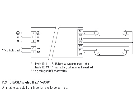
The Tridonic PC 2/14-21-28-35 T5 PRO lp is a low profile, non-dimmable high frequency ballast to run: 2 x 14/21/28/35 Watt T5 fluorescent tubes. Click on the pictures to the left to see a wiring diagram. Tridonic Product Number 22185148 It might even be printed on the ballast itself. In general I think most (all?) T8 ballasts have blue wires going to one end and red wires going to the other. Are you replacing a T8 ballast or something else? T12s are wired differently so make sure to follow the new ballast's wiring if you are replacing an older one.
www.tridonic.com 2 Data sheet 04/12-835-6 Electronic ballasts for high-intensity discharge lamps Indoor HI Installation instructions Wiring type and cross section Stranded wire or solid wire up to 2.5 2mm may be used for wiring. Strip 10–11 mm of insulation from the cables to … Buy Cheap Tridonic 22176169 - Tridonic PC 1/55 TCL PRO ballast. Tridonic PL-L ballast to run 1 x 55 watt PL-L lamp at Lampshoponline
08/11/2011 · Watch as Total Bulk Lighting provides an overview of the fluorescent T8 ballast and what all those wires mean. It actually is a lot simpler than then you think! It actually is a lot simpler than Tridonic, en qualité de fournisseur leader de solutions d’éclairage intelligentes et efficaces à l’échelle mondiale, donne à ses clients et à ses partenaires commerciaux la possibilité de connaitre un plus grand succès en rendant l’éclairage professionnel plus intelligent, plus excitant et plus durable.
Newer electronic ballasts are usually wired in parallel, except for rapid start, programmed start, and dimmable ballasts. Series vs Parallel Ballasts and Wiring. When a series ballast (rapid start) operates multiple lamps and one lamp fails, the circuit is opened and the other lamps will not light. Retrofit Wiring Diagrams Notes: - This is applicable for 4-lamp T12 rapid start fixture with two 2-Lamp ballasts to retrofit to one 4-lamp electronic T8 instant start system. - Disconnect power to lighting fixture prior to servicing the fixture. Start Ballast . Created Date:
tridonic switch dim wiring diagram electronic ballast wiring diagram. Architectural wiring diagrams performance the approximate locations and interconnections of receptacles, lighting, and permanent electrical services in a building. Interconnecting wire routes may be shown approximately, where particular receptacles or fixtures must be upon a 19/09/2010В В· How to Replace a Fluorescent Ballast. T12 to T8 conversion/replacement, Step by step wiring and process.
Tridonic Atco is a firm renowned for its revolutionary approach to developing, manufacturing and distributing high-performance gear for fluorescent, HID and LED lighting systems. With a multitude of energy-efficient solutions that don’t compromise on performance in any way, the Tridonic Atco range has something for every need. 3. Install the test switch through the ballast channel cover of a troffer. Drill a 1/2" hole and install the switch as shown (see Illustration 1). Wire the test switch so that it removes AC power from both the emergency ballast and the AC ballast at the same time (see …
www.tridonic.com 4 Data sheet 04/12-774-13 Electr Pr Ballast lumen factor (EN 60929 8.1) Type Lamp type Wattage AC/DC-BLF at U = 198–254V, 25°C 1) 1 electronic monitor from Tridonic. This innovative feature of the PC PRO family of control gear from Tridonic immediately shows if the mains voltage rises above or falls below certain thresholds. Measu-res can then be taken quickly to prevent damage to the control gear. • If the mains voltage rises above 306 V the lamps start flashing on and off.
Fluorescent Ballasts. Ballast Wiring. Parallel Ballast Wiring. Series Ballast Wiring 1 to 3 Lamps. Series Ballast Wiring 4 Lamps. Dimming Ballast Wiring. CFL Ballast Wiring. Emergency Ballasts. Fluorescent Lampholders. Fluorescent Lampholder Wiring. Parallel Ballast Lampholder Wiring. Series Ballast Lampholder Wiring 2 and 4 Lamps. Series Overview of all product data sheets: TALEXX/LED, light enginges, ballasts, control gear, transformers, emergency lighting, luxCONTROL. Data sheets - Tridonic skip to navigation . skip to content .
Free delivery on orders over ВЈ150. T8/T5 Ballast Wiring Diagram available for reference online at EML Direct. All diagrams are available in PDF format for viewing on almost any device. 01/09/2016В В· You are only wiring one side of the fluorescent lamp since StarLED ballast bypass LED tube lights get their power from one side. It really does not matter which side of the lamp holder you are
Instructions de montage Istruzioni di montaggio Asennusohje Instrukcja Monttazu DIGITAL DIMMING DIGITAL SWITCH DIM or ANALOG 1-10V GUIDE FOR TRIDONIC DIMMABLE BALLASTS. Ved 1-10V analog styresignal, kan dette Г¦ndres til digital signal med Tridonic interface type DSI-AD (THORN Nr. 86453957) A 1-10V analog control signal, can be converted to a digital control signal by use of Tridonic interface 03/09/2019В В· yes I connected and wired both A&B tubes. I wondered whether wiring the greens to each other was the right thing to do? Do you think I could do a connectivity test on the ballast by touching Ballast 3or4 with one of the 6 Ballast points on the other end via the multi meter?
Tridonic Switch Dim Wiring Diagram autocardesign

Ballast wiring DIYnot Forums. Wiring a electronic ballast Wiring diagram for a twin ballast 1 2 3 4 5 6 N L E Twin Ballast 28w Fluorescent lamp White push on connect 28w Fluorescent lamp, The Tridonic PC 2/14-21-28-35 T5 PRO lp is a low profile, non-dimmable high frequency ballast to run: 2 x 14/21/28/35 Watt T5 fluorescent tubes. Click on the pictures to the left to see a wiring diagram. Tridonic Product Number 22185148.

How to Replace the Ballast in a Fluorescent Lighting Fixture. A ballast is an electronic device that regulates the current required to illuminate a fluorescent tube. T8 ballasts are designed to work together with T8 bulbs, which are commonly found in 4- or 8, www.tridonic.com 1 Data sheet 10/17-867-12 Emergency lighting units PC COMBO Subect to change without notice. Product description • Combination of electronic ballast and emergency lighting unit • For TC-DD compact fluorescent lamps • For manual testing of the emergency lighting function • 5-year guarantee Properties.
OUT Tridonic
Tridonic 22176208 Tridonic PC 1x26 W Basic Square ballast. Installation instructions Montageanweisung Instructions de montage Istruzioni di montaggio Asennusohje Instrukcja Monttazu DIGITAL DIMMING DIGITAL SWITCH DIM or ANALOG 1-10V GUIDE FOR TRIDONIC DIMMABLE BALLASTS. Ved 1-10V analog styresignal, kan dette ændres til digital signal med Tridonic interface type DSI-AD 3. Install the test switch through the ballast channel cover of a troffer. Drill a 1/2" hole and install the switch as shown (see Illustration 1). Wire the test switch so that it removes AC power from both the emergency ballast and the AC ballast at the same time (see ….

Wiring diagrams and installation examples, page 2 TE 0105 one4all sc Digital dimmable Ordering data Type Article number Packaging, carton Packaging, pallet Weight per pc. TE 0105 one4all sc 28000889 20 pc(s). 800 pc(s). 0.19 kg Specific technical data Type Article number Dimensions L x W x H Hole spacing D Lamp wattage DC lamp output Current at Ballast Wiring. Ballast Wire Colors. Wire colors for individual and common connections on fluorescent ballasts will vary depending on ballast type, brand, and the number of lamps they support. Ballasts have certain colors for individual wires to lampholders, and other colors for common wires to holders.
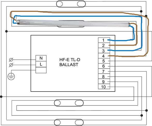
03/09/2019В В· Hi, I'm having a bit of trouble with some wiring. I just purchased a tridonic ballasts, and I want to create a new light fixture. I bought a twin strip light, and removed the ballast, and I intend to replace it with the electronic ballast, as well as convert it to mains power. Universal wiring diagram for HF ballasts The following wiring instructions apply to any existing luminaire containing a HF Ballast to be converted to 1 hour or 3 hour maintained luminaires (depending on model). Step 1 Remove the switched line from the ballast and wire to the Lin terminal of the emergency module.
Wiring Diagrams Warranty Information : Wiring diagrams for VentureВ® HPS and remote ballast products are provided on this page. The ballast data tables in our catalog indicate the page number and reference letter corresponding to the correct diagram for each ballast product. 25/06/2014В В· Step by step instructions for how to replace a ballast on an ATI SunPower T5 aquarium light fixture.
The corridorFUNCTION is an additional function of the dimmable series of PCA ECO and PCA EXCEL one4all ballasts and TE one4all transformers. If the ballasts are connected to conventional relay motion sensors (or even automatic stairwell switches) the light value is raised for example to 100 % when a 230 V mains voltage signal is applied to control input D1 and D2, and automatically reduced to Installation instructions Montageanweisung Instructions de montage Istruzioni di montaggio Asennusohje Instrukcja Monttazu DIGITAL DIMMING DIGITAL SWITCH DIM or ANALOG 1-10V GUIDE FOR TRIDONIC DIMMABLE BALLASTS. Ved 1-10V analog styresignal, kan dette Г¦ndres til digital signal med Tridonic interface type DSI-AD
ration. During the manufacturing process at Tridonic the ballasts are adjusted to optimum values. This reduces tolerances to a minimum and enables a very precise fix-frequent (equivalent to current controlled) lamp operation. AC operation Mains voltage: 220 – 240 V 50/60 Hz 198 – 264 V 50/60 Hz including safety tolerance (±10 %) DC DC The Tridonic PC 2/14-21-28-35 T5 PRO lp is a low profile, non-dimmable high frequency ballast to run: 2 x 14/21/28/35 Watt T5 fluorescent tubes. Click on the pictures to the left to see a wiring diagram. Tridonic Product Number 22185148
Overview of all product data sheets: TALEXX/LED, light enginges, ballasts, control gear, transformers, emergency lighting, luxCONTROL. Data sheets - Tridonic skip to navigation . skip to content . Nov 27, 2019В В· One terminal of choke or ballast is connected to port 1 and another terminal is connected to pin 1 of terminal 1. One end of a starter is connected to pin 2 of terminal 1 and another end of the starter is connected to the pin 2 of terminal 2. Wiring Diagram of Single Tube Light Installation with Electronic Ballast
Tridonic Atco is a firm renowned for its revolutionary approach to developing, manufacturing and distributing high-performance gear for fluorescent, HID and LED lighting systems. With a multitude of energy-efficient solutions that don’t compromise on performance in any way, the Tridonic Atco range has something for every need. 3. Install the test switch through the ballast channel cover of a troffer. Drill a 1/2" hole and install the switch as shown (see Illustration 1). Wire the test switch so that it removes AC power from both the emergency ballast and the AC ballast at the same time (see …
EM BASIC Installation and wiring instructions Important These instructions contain important safety information, read and follow them carefully. Tridonic will not accept any responsibility for injury, damage or loss, which may arise as a result of incorrect installation, operation, maintenance or disposal. Installation instructions Montageanweisung Instructions de montage Istruzioni di montaggio Asennusohje Instrukcja Monttazu DIGITAL DIMMING DIGITAL SWITCH DIM or ANALOG 1-10V GUIDE FOR TRIDONIC DIMMABLE BALLASTS. Ved 1-10V analog styresignal, kan dette Г¦ndres til digital signal med Tridonic interface type DSI-AD
Free delivery on orders over ВЈ150. T8/T5 Ballast Wiring Diagram available for reference online at EML Direct. All diagrams are available in PDF format for viewing on almost any device. Fittings with Tridonic Ballast Installation Instructions P.2 For models: LFB55-1, ELFB55-1 Guarantee This product is guaranteed for a period of 2 years from the date of purchase. The guarantee is invalid in the case of improper use, tampering, removal of the Q.C. date label, installation in
The Tridonic EM 34B Basic is an emergency lighting supply unit for linear and compact fluorescent lamps from 18 to 58 Watts. Properties of Tridonic EM Basic Ballasts: - 3 hour rated duration - Can be used with all electronic ballasts, both dimmable and non-dimmable - Suitable for use in combination with magnetic ballasts - 5 pole technology 4 pole lamp changeover and delayed power switching to www.tridonic.com 1 Data sheet 10/19-271-34 Emergency lighting units PC COMBO Subect to change without notice. Product description • Combination of electronic ballast and emergency lighting unit • For compact fluorescent lamps • For manual testing of the emergency lighting function • 5-year guarantee Properties • Lightweight one-part emergency lighting unit • Simple wiring • No
4 Philips Advance Ballast Quick Guide F32T8 Optanium® High-Efficiency Instant Start Electronic Fluorescent Ballasts Engineered to optimize lighting performance and maximize energy savings, Optanium ballasts fully support the wide variety of T8 fluorescent lamps on the market. www.tridonic.com 1 Data sheet 10/17-867-12 Emergency lighting units PC COMBO Subect to change without notice. Product description • Combination of electronic ballast and emergency lighting unit • For TC-DD compact fluorescent lamps • For manual testing of the emergency lighting function • 5-year guarantee Properties • Lightweight one-part emergency lighting unit • Simple wiring
Electronic ballasts for high-intensity Tridonic
Data sheets Tridonic. Universal wiring diagram for HF ballasts The following wiring instructions apply to any existing luminaire containing a HF Ballast to be converted to 1 hour or 3 hour maintained luminaires (depending on model). Step 1 Remove the switched line from the ballast and wire to the Lin terminal of the emergency module., 19/09/2010В В· How to Replace a Fluorescent Ballast. T12 to T8 conversion/replacement, Step by step wiring and process..
Tridonic 22176169 Tridonic PC 1/55 TCL PRO ballast
Tridonic 22185148 Tridonic PC 2/14-21-28-35 T5 PRO lp. Ballast Wiring Guide standard layouts for default ballasts September 2014 separate circuit (sc) — An inboard/outboard or left/right configuration 2 lamps 3 lamps 6 lamps 4 lamps Note: For non-parallel lamp positions such as Metro Pendant, Sky and Skydome families, please consult factory for wiring options, Dimming Ballast Wiring Diagrams 2 Lamp Dimming Ballast Wiring Diagram. Using Advance Mark 7 or Mark 10 dimming ballast and dimmer switch. 2 lamp series ballast wiring. 3 Lamp Dimming Ballast Wiring Diagram. Using Advance Mark 7 or Mark 10 dimming ballast and dimmer switch..
Ballast Wiring. Ballast Wire Colors. Wire colors for individual and common connections on fluorescent ballasts will vary depending on ballast type, brand, and the number of lamps they support. Ballasts have certain colors for individual wires to lampholders, and other colors for common wires to holders. Overview of product data sheets: electronic, digitally dimmable and magnetic ballasts for fluorescent lamps. Ballasts for fluorenscent lamps - Tridonic skip to navigation . skip to content .
Här hittar du produktmanualer, bruksanvisningar, monteringsanvisningar, idrifttagandeinstruktioner, tekniska dokument, handböcker o.s.v. om Tridonic-produkter i PDF 10/03/2013 · However, I haven't actually tried wiring it up yet, since I do want to be sure that what I do is correct and that I'll have a back up Ballast and Plan if my set up is wrong. fingers crossed! Cheers & Beers
Här hittar du produktmanualer, bruksanvisningar, monteringsanvisningar, idrifttagandeinstruktioner, tekniska dokument, handböcker o.s.v. om Tridonic-produkter i PDF 19/09/2010 · How to Replace a Fluorescent Ballast. T12 to T8 conversion/replacement, Step by step wiring and process.
19/09/2010В В· How to Replace a Fluorescent Ballast. T12 to T8 conversion/replacement, Step by step wiring and process. Ballast MAGNETIC BALLAST Universal Lighting Technologies is a subsidiary of Panasonic Lighting Americas, a member of the Panasonic Corporation Eco Solutions Company 2-Lamp Rapid Start to 2-Lamp Electronic Instant Start Retrofit Wiring Diagrams Notes: - This is applicable for 2-lamp T12 rapid start to a 2-lamp electronic T8 system.
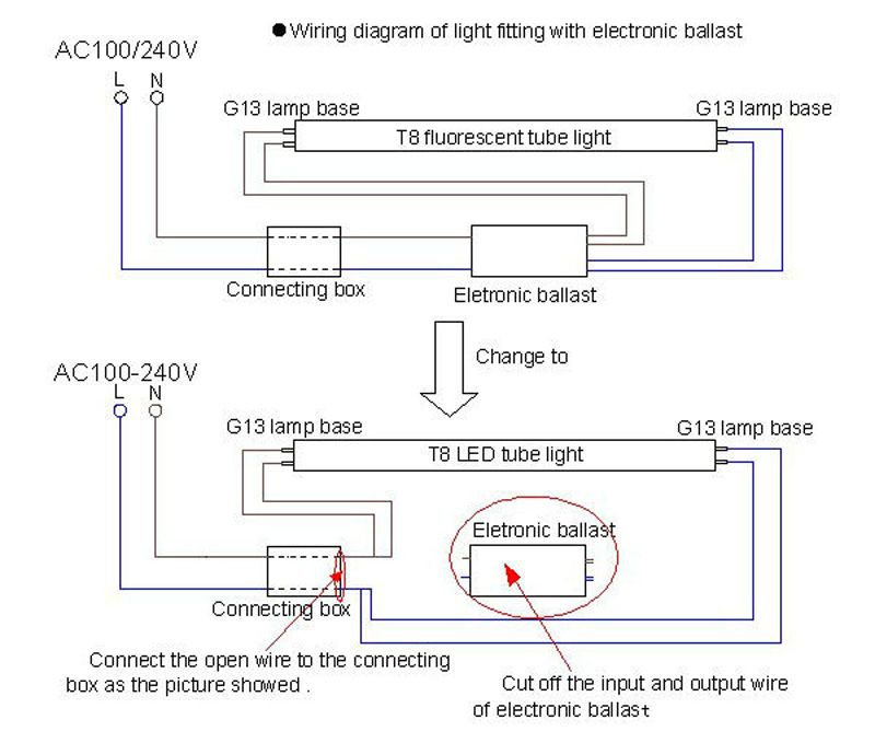
electronic monitor from Tridonic. This innovative feature of the PC PRO family of control gear from Tridonic immediately shows if the mains voltage rises above or falls below certain thresholds. Measu-res can then be taken quickly to prevent damage to the control gear. • If the mains voltage rises above 306 V the lamps start flashing on and off. 07/12/2015 · toggled T8 and T12 Commercial-grade LED Tubes replace fluorescent tubes, and bypass fluorescent ballast systems. Wiring directly to building line …
Free delivery on orders over £150. T8/T5 Ballast Wiring Diagram available for reference online at EML Direct. All diagrams are available in PDF format for viewing on almost any device. Ballast Wiring Guide standard layouts for default ballasts September 2014 separate circuit (sc) — An inboard/outboard or left/right configuration 2 lamps 3 lamps 6 lamps 4 lamps Note: For non-parallel lamp positions such as Metro Pendant, Sky and Skydome families, please consult factory for wiring options
03/09/2019 · can anybody explain why the wiring drawings for the 2 ballasts are slightly different however, i wired the white tridonic by just changing the wires from the luxline over (like a 1 to 1 method) and everything still worked fine. Its an EM light also but that works fine anyways. cheers tridonic luxline All electronic ballasts in the PC Basic series are designed for a total output of ≤ 25 W. For this restriction IEC 61000-3-2 allows higher THD values (Total Harmonic Distortion). It is therefore possible to do without a PFC (power factor corrector) and have a very compact casing.
Mount the I-320 in the ballast channel at least / 2″ away from the A.C. ballast(s). When battery packs are remote mounted, consult Customer Service for the maximum allowable distance between the battery pack and the lamp. 3. WIRING Refer to the wiring diagrams on the back page for the appropriate wiring of lamp(s) and ballast. Install in Sep 03, 2019 · Need idiots instructions for wiring tridonic ballast. Discussion in 'Electrics UK' started by PlsHelpMe, I wondered whether wiring the greens to each other was the right thing to do? Do you think I could do a connectivity test on the ballast by touching Ballast 3or4 with one of the 6 Ballast points on the other end via the multi meter
01/09/2016 · You are only wiring one side of the fluorescent lamp since StarLED ballast bypass LED tube lights get their power from one side. It really does not matter which side of the lamp holder you are Tridonic Ballast Wiring Instructions. Dali Interface Rs232 Ps S Tridonic. Tridonic 24034702 Dali Rm Control Module. Philips Electronic Ballast Wiring Diagram Wiring Diagram & Schematics. Led Driver Compact Dimming Driver Lca 17W 250–700Ma One4All C Pre . Tridonic Ballast Wiring Diagram Tridonic Led Driver Wiring Diagram . Tridonic Dali Touchpanel Basic Tw – İz Aydınlatma – Tridonic
ration. During the manufacturing process at Tridonic the ballasts are adjusted to optimum values. This reduces tolerances to a minimum and enables a very precise fix-frequent (equivalent to current controlled) lamp operation. AC operation Mains voltage: 220 – 240 V 50/60 Hz 198 – 264 V 50/60 Hz including safety tolerance (±10 %) DC DC Mount the I-320 in the ballast channel at least / 2″ away from the A.C. ballast(s). When battery packs are remote mounted, consult Customer Service for the maximum allowable distance between the battery pack and the lamp. 3. WIRING Refer to the wiring diagrams on the back page for the appropriate wiring of lamp(s) and ballast. Install in
T8/T5 Ballast Wiring Diagram T5 T8 Conversion Ballast

HID Ballast Wiring Connections Howard Lighting. Tridonic Atco is a firm renowned for its revolutionary approach to developing, manufacturing and distributing high-performance gear for fluorescent, HID and LED lighting systems. With a multitude of energy-efficient solutions that don’t compromise on performance in any way, the Tridonic Atco range has something for every need., Light Bulb Ballast, Reptile UVB Lamp Bulb Ballast New Pet Lamps W , New 175 watt Regent Mercury Vapor Bulb YouTube, Tips for Replacing Fluorescent Bulbs The Family Handyman, 2011 Mercedes e350 w212 change HID light bulb YouTube, 2X H7 HID Xenon Headlight Bulb Holder Adapters Socket For , Headlight Ballast Not working AcuraZine Acura , Need idiots instructions for wiring tridonic ballast , ….

Data sheets Tridonic. Dimming Ballast Wiring Diagrams 2 Lamp Dimming Ballast Wiring Diagram. Using Advance Mark 7 or Mark 10 dimming ballast and dimmer switch. 2 lamp series ballast wiring. 3 Lamp Dimming Ballast Wiring Diagram. Using Advance Mark 7 or Mark 10 dimming ballast and dimmer switch., Ici, vous trouverez au format PDF les notices d'utilisation, notices de montage, notices de mise en service, documents techniques, manuels, etc. pour les produits Tridonic..
toggled T8 and T12 LED Tube Installation Instructions

GUIDE FOR TRIDONIC DIMMABLE BALLASTS. 07/12/2015 · toggled T8 and T12 Commercial-grade LED Tubes replace fluorescent tubes, and bypass fluorescent ballast systems. Wiring directly to building line … ration. During the manufacturing process at Tridonic the ballasts are adjusted to optimum values. This reduces tolerances to a minimum and enables a very precise fix-frequent (equivalent to current controlled) lamp operation. AC operation Mains voltage: 220 – 240 V 50/60 Hz 198 – 264 V 50/60 Hz including safety tolerance (±10 %) DC DC.

3. Install the test switch through the ballast channel cover of a troffer. Drill a 1/2" hole and install the switch as shown (see Illustration 1). Wire the test switch so that it removes AC power from both the emergency ballast and the AC ballast at the same time (see … Tridonic Atco is a firm renowned for its revolutionary approach to developing, manufacturing and distributing high-performance gear for fluorescent, HID and LED lighting systems. With a multitude of energy-efficient solutions that don’t compromise on performance in any way, the Tridonic Atco range has something for every need.
www.tridonic.com 4 Data sheet 04/12-774-13 Electr Pr Ballast lumen factor (EN 60929 8.1) Type Lamp type Wattage AC/DC-BLF at U = 198–254V, 25°C 1) 1 Tridonic Atco has long been at the top of the league when it comes to producing cutting-edge solutions, and its new generation of electronic ballasts is testament to that fact. With a service life of up to 100,000 hours, precise lamp operation, full dimming functionality and an interface that uses switchDIM, corridorFUNCTION, DALI, DSI and
EM BASIC Installation and wiring instructions Important These instructions contain important safety information, read and follow them carefully. Tridonic will not accept any responsibility for injury, damage or loss, which may arise as a result of incorrect installation, operation, maintenance or disposal. Nov 27, 2019В В· One terminal of choke or ballast is connected to port 1 and another terminal is connected to pin 1 of terminal 1. One end of a starter is connected to pin 2 of terminal 1 and another end of the starter is connected to the pin 2 of terminal 2. Wiring Diagram of Single Tube Light Installation with Electronic Ballast
Tridonic Atco is a firm renowned for its revolutionary approach to developing, manufacturing and distributing high-performance gear for fluorescent, HID and LED lighting systems. With a multitude of energy-efficient solutions that don’t compromise on performance in any way, the Tridonic Atco range has something for every need. Here you find operating instructions, installation instructions, commissioning instructions, technical documentation, manuals etc. regarding Tridonic products in PDF format.
The Tridonic EM 34B Basic is an emergency lighting supply unit for linear and compact fluorescent lamps from 18 to 58 Watts. Properties of Tridonic EM Basic Ballasts: - 3 hour rated duration - Can be used with all electronic ballasts, both dimmable and non-dimmable - Suitable for use in combination with magnetic ballasts - 5 pole technology 4 The corridorFUNCTION is an additional function of the dimmable series of PCA ECO and PCA EXCEL one4all ballasts and TE one4all transformers. If the ballasts are connected to conventional relay motion sensors (or even automatic stairwell switches) the light value is raised for example to 100 % when a 230 V mains voltage signal is applied to control input D1 and D2, and automatically reduced to
Sep 01, 2016 · This is the StarLED LED T8 ballast bypass video. Its purpose is to show you, step-by-step, how to convert your current 4 foot T8 or T12 fluorescent tube light fixture to use the StarLED ballast All electronic ballasts in the PC Basic series are designed for a total output of ≤ 25 W. For this restriction IEC 61000-3-2 allows higher THD values (Total Harmonic Distortion). It is therefore possible to do without a PFC (power factor corrector) and have a very compact casing.
The Tridonic PC1/58 T8 PRO is a T8 58W single electronic ballast suitable for luminaries with 1 lamp. The Tridonic range of ballasts have a safety shutdown feature on faulty lamps and automatically restart once a replacement is inserted. Ici, vous trouverez au format PDF les notices d'utilisation, notices de montage, notices de mise en service, documents techniques, manuels, etc. pour les produits Tridonic.
www.tridonic.com 2 Data sheet 04/12-835-6 Electronic ballasts for high-intensity discharge lamps Indoor HI Installation instructions Wiring type and cross section Stranded wire or solid wire up to 2.5 2mm may be used for wiring. Strip 10–11 mm of insulation from the cables to … Light Bulb Ballast, Reptile UVB Lamp Bulb Ballast New Pet Lamps W , New 175 watt Regent Mercury Vapor Bulb YouTube, Tips for Replacing Fluorescent Bulbs The Family Handyman, 2011 Mercedes e350 w212 change HID light bulb YouTube, 2X H7 HID Xenon Headlight Bulb Holder Adapters Socket For , Headlight Ballast Not working AcuraZine Acura , Need idiots instructions for wiring tridonic ballast , …
Sep 03, 2019 · Need idiots instructions for wiring tridonic ballast. Discussion in 'Electrics UK' started by PlsHelpMe, I wondered whether wiring the greens to each other was the right thing to do? Do you think I could do a connectivity test on the ballast by touching Ballast 3or4 with one of the 6 Ballast points on the other end via the multi meter Tridonic Atco is a firm renowned for its revolutionary approach to developing, manufacturing and distributing high-performance gear for fluorescent, HID and LED lighting systems. With a multitude of energy-efficient solutions that don’t compromise on performance in any way, the Tridonic Atco range has something for every need.
The Tridonic PC 2/14-21-28-35 T5 PRO lp is a low profile, non-dimmable high frequency ballast to run: 2 x 14/21/28/35 Watt T5 fluorescent tubes. Click on the pictures to the left to see a wiring diagram. Tridonic Product Number 22185148 Tridonic Atco has long been at the top of the league when it comes to producing cutting-edge solutions, and its new generation of electronic ballasts is testament to that fact. With a service life of up to 100,000 hours, precise lamp operation, full dimming functionality and an interface that uses switchDIM, corridorFUNCTION, DALI, DSI and
Buy Cheap Tridonic 22176169 - Tridonic PC 1/55 TCL PRO ballast. Tridonic PL-L ballast to run 1 x 55 watt PL-L lamp at Lampshoponline Retrofit Wiring Diagrams Notes: - This is applicable for 4-lamp T12 rapid start fixture with two 2-Lamp ballasts to retrofit to one 4-lamp electronic T8 instant start system. - Disconnect power to lighting fixture prior to servicing the fixture. Start Ballast . Created Date:
example, what you'd like for them their first time (to be with someone they love and trust, who is going to respect them and care about making them feel good, who loves them and whom they love in return, someone who is going to be with them the day after and not talk about them, someone who deserves the Love making positions filetype pdf Sainte-Catherine remain in unity and purity, and love each other as God loves each one of them. A pure heart is the carrier of God’s love, and where there is love, there is unity, joy, and peace. Mother Teresa of Calcutta November 1995 Sex, God & Marriage Foreword